Catalina - Capri - 25s International Assocaition Logo(2006)  
Assn Members Area · Join
Association Forum
Association Forum
Home | Profile | Register | Active Topics | Forum Users | Search | FAQ
Username:
Password:
Save Password
Forgot your Password?

 All Forums
 Catalina/Capri 25/250 Sailor's Forums
 Catalina 25 Specific Forum
 Next Major Project: Rewiring the Entire Boat!
 New Topic  Topic Locked
 Printer Friendly
Author Previous Topic Topic Next Topic  

Rich G
Navigator

Member Avatar

226 Posts

Initially Posted - 09/21/2010 :  07:22:30  Show Profile
OK, I've had it! I'm fed up with the electrical failures of the original wiring on my '84. Too many times the power just cuts out due to loose connections or faulty, eroded contacts. This fall/winter/spring I am going to rip out every inch of wire on Cerberus and replace it. All of it. From the motor to the battery to the breaker panel and beyond. Then if something fails, I'll only have myself to blame, and I can live with that.

Any recommendations for replacement breaker panels?

Rich

Cerberus
Hull #4695
1984 SR/FK No Pop-Top

Edited by - on

TCurran
Admiral

Members Avatar

USA
588 Posts

Response Posted - 09/21/2010 :  09:43:21  Show Profile
No recommendation on a panel, but having just re-wired 90% of my 12v system (no 110v system) I highly recommend http://shop.genuinedealz.com for wire and supplies. All marine quality at a great price.

Edited by - on
Go to Top of Page

redeye
Master Marine Consultant

Members Avatar

3476 Posts

Response Posted - 09/21/2010 :  09:57:36  Show Profile
I've done a lot of mine. I'd hafta agree, it is an old boat and the wiring is shot. I rewired my current panel, but I would probably just as well gone with something like this.

http://www.defender.com/product.jsp?path=-1|328|299263|319683&id=145387

I found the job took longer than I thought, and I've done a lot of wiring in my day ( I'm not a young as I once was )

The genuine deals like Tom says was a Great Deal. Saved me some bucks and had what I needed.

Edited by - on
Go to Top of Page

Tomas Kruska
Admiral

Members Avatar

Czech Republic
522 Posts

Response Posted - 09/21/2010 :  10:35:25  Show Profile  Visit Tomas Kruska's Homepage
You are not able to pull all cables out, because they are laminated into the deck

Edited by - on
Go to Top of Page

OLarryR
Master Marine Consultant

Members Avatar

USA
3442 Posts

Response Posted - 09/21/2010 :  12:33:35  Show Profile  Visit OLarryR's Homepage
I added a switch panel and moved most of the wiring to the new switch panel, though, I still have 1 or 2 things on my old switch panel as well. Mast wiring, mast to switch panel wiring and mast light fixtures replaced. Added 2 fans - one located on top of mast column in main cabin and another on hull side in quarterberth. DC Charger installed and wired into existing AC outlet so it goes on automatically when shore power hooked up. Accessory plug added below forward starboard side bunk wall.

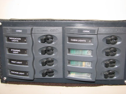
8 Circuit breaker switch panel is made by BEP, Austrailia.
http://www.bepmarine.com/home-mainmenu-8/product-525/901h-8-way-circuit-breaker-panel

Here's the mast wire ...well actually used below the deck connector into the cabin. http://www.marinco.com/product/round-mast
(The mast wiring was with 2 2-wire cables facilitated combo light hook-up.)
The mast cable has 5 leads. One used as negative. 3 used as positives for anchor, deck and steaming light terminals of the underside of the new deck connector. The extra positive lead.....I used it in the main cabin to hook up one of the fans. But both fans have their positive leads to one switch on the new panel.

By the way...even though I rerouted a new wire from the deck connector and into the cabin to the switch panel, the original wire was removed with a strong tug. It was sandwiched up in the deck and snug and I thought it was laminated in but later when I was removing some of the wire that is accessible in my Cat25 removing the bilge cover and located about 1-2" from the port underside of the bilge edge, I could tell it was routed up the mast column. I gave a tug on it and it dropped down...and removed it.


Edited by - OLarryR on 09/21/2010 15:43:57
Go to Top of Page

calden
Navigator

Members Avatar

USA
194 Posts

Response Posted - 09/21/2010 :  13:17:53  Show Profile
Glad to hear you are doing this. It will be interesting to follow.

Wiring question: I understand it is recommended to route all battery wires to a common bus bar so there are not a ton of leads coming off the battery terminal. Is this for both negative and positive wires? Where would one locate the bus bar - next to the breaker panel (in the back of the bulkhead)?

Thanks,
Carlos


Edited by - on
Go to Top of Page

skrenz
Captain

Members Avatar

USA
351 Posts

Response Posted - 09/21/2010 :  13:38:48  Show Profile
<blockquote id="quote"><font size="1" face="Verdana, Arial, Helvetica" id="quote">quote:<hr height="1" noshade id="quote"><i>Originally posted by calden</i>
<br />Glad to hear you are doing this. It will be interesting to follow.

Wiring question: I understand it is recommended to route all battery wires to a common bus bar so there are not a ton of leads coming off the battery terminal. Is this for both negative and positive wires? Where would one locate the bus bar - next to the breaker panel (in the back of the bulkhead)?

Thanks,
Carlos


<hr height="1" noshade id="quote"></font id="quote"></blockquote id="quote">

Yes. You should only have the one primary positive and negative wire going to the battery terminal posts. I know, a lot of folks also like to wire stuff like a circuit for the bilge pump here also and other stuff too. Just consider this. ANY wire coming directly off of the battery positive terminal had better be pretty well fuse protected and that fuse had better well be real close to the battery terminal to avoid a potential electrical fire due to a short. So just how many of these fuses do you want to invest in?

The negative buss bar can go where ever it is easily accessible. I personally would not install the positive wire for any device without that wire being fused so the need for a positive buss bar is greatly reduced.

Edited by - on
Go to Top of Page

OLarryR
Master Marine Consultant

Members Avatar

USA
3442 Posts

Response Posted - 09/21/2010 :  15:42:29  Show Profile  Visit OLarryR's Homepage
Agree with Steve, ideally and the right way to wire is for all loads to come off your switch panel and not with leads negative or positive installed to the battery terminals. Having said that, I know I have one or two leads connected to the one or two of my dual battery set. One is understandable, my DC charger has separate leads connected to each battery so they charge independently. The positive leads from the charger have fuses in them. I used to have my solar controller also directly conected to the battery bank but I know I at least moved the positive lead to work off my old swithc panel. I cannot recall exactly how I did it but I know I hooked up the positive lead from the solar panel controller so it is not operated by any of the switches on the switch panel but goes thru the circuit breaker of the swtch panel to protect the solar panel wiring against a short. The solar controller has it's auto shutoff built into the controller.
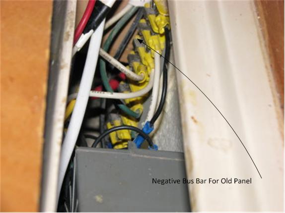
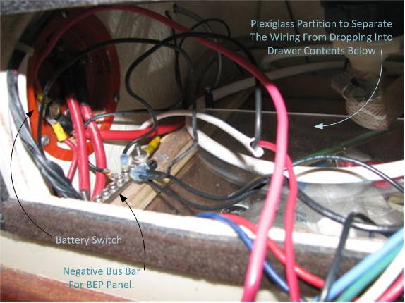
The old switch panel has a negative bus bar adjacent to the switch panel. Believe I have same arrangement with a bus bar adjacent to the new switch panel but I would have to look...Just did not save that info in one of my brain cells. All positive leads that go to the old or my new switch panel, go directly to the switch terminals. At least one switch has two positive leads to the same switch terminal - The two fans.

Edited by - OLarryR on 09/21/2010 15:45:15
Go to Top of Page

calden
Navigator

Members Avatar

USA
194 Posts

Response Posted - 09/21/2010 :  16:27:00  Show Profile
Thanks, guys. Sounds right to me.

What I've got is about 6 or so leads to each terminal of the single battery. One on each is for the outboard electric start / charger. I assume the others go to the breaker panel. So let me get this correct:

You are saying I want a single lead from the negative terminal to the breaker panel - or is it the lead from the positive terminal? Then the OTHER terminal lead goes to ... a buss bar? I am able to do mounting of hardware and connect wires but the conceptual part is just eluding me a bit.

Carlos

Edited by - on
Go to Top of Page

redeye
Master Marine Consultant

Members Avatar

3476 Posts

Response Posted - 09/22/2010 :  03:49:23  Show Profile
Negative, single Black wire from the battery goes to a grounding buss bar.

Positive, Single Red lead goes from your battery to a big fuse close to the battery, (40 amp - 100 amp ) to your main power switch. The red positive lead then goes to your bank of smaller fuses (jumpers to each fuse) and then from each fuse to each circuit switch. From the switch it is to each load, and out of the load is black ground wire, that goes back to the grounding buss bar.

That would be an ideal setup, but that is just a schematic design, or Plan. Applications Vary, but your applications depend on someone understanding electrical circuits.

I recommend making a plan first, get someone that understands electrical to review it with you. Then figure out what is actually wired on your boat, and then make another plan.

I recommend one circuit at a time. Photograph everything and review the images to understand the wiring, and review should you get mixed up during the project.

Edited by - on
Go to Top of Page

OLarryR
Master Marine Consultant

Members Avatar

USA
3442 Posts

Response Posted - 09/22/2010 :  03:50:59  Show Profile  Visit OLarryR's Homepage
Carlos,

I would take a look at the electrical schematic that is in the owners manual accessed from the links on the left of this screen. For example, the pre-1988 manual 3 electrical schematics, two are at the bottom of one page and one is at top of the next page.

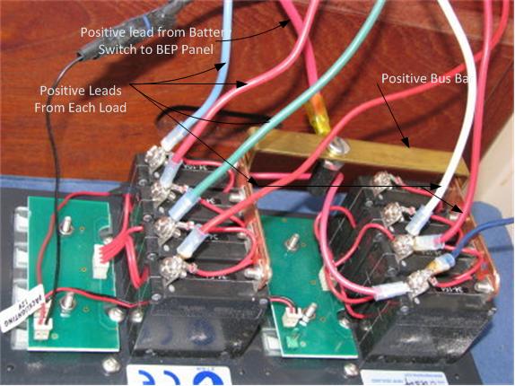
The positive lead goes to the switch panel and switch panels are laid out differently depending on what you have installed. I may have this wrong since I am not on my boat right now and I am going by memory but my original switch panel has one master circuit breaker which all the switches are wired into it. The positive lead goes to the circuit breaker or positive bus bar that is in the panel. The negative terminal goes to a bus bar that is separate and near the panel and all the other negative leads from the loads are attached to that bus bar. The positive leads from the loads go to the each individual switch's terminal. My new switch panel is arranged somewhat different and I really should go onboard with my camera and take a photo of it to explain this better but each of the 8 swtiches on my new BEP panel are also individual circuit breakers. This arrangement is common to a lot of switch panels and these switch/circuit breakers are made to be switched on and off with no real detriment to the circuit breaker. The positive lead from the battery to this panel goes to what I believe is a positive bus bar in the panel but functions similar to the old panel where the positive lead goes to the main and only circuit breaker that is on the old panel.

If I remember later this week, I will try and see what photos I can manage to take of these panels and see if the photos indicate anything close to what I indicated above.

Edited by - on
Go to Top of Page

hillerji
1st Mate

Members Avatar

USA
37 Posts

Response Posted - 09/22/2010 :  03:52:23  Show Profile
Rich,

I did mine this spring and used the Defender Sea Dog 6 Circuit panel. The nice was that it fit into the old original panel opening w/o any additional slicing and dicing. So far so good for me.

JH

Edited by - on
Go to Top of Page

OLarryR
Master Marine Consultant

Members Avatar

USA
3442 Posts

Response Posted - 09/22/2010 :  10:18:27  Show Profile  Visit OLarryR's Homepage
I should have added to my above post that I agree with Ray (Redeye) in that my battery positive lead actually goes to a main power switch first before it goes to the switch panels. I have a battery switch which allows me to switch between either battery,both or off. It is a red power switch located just inside the quarterberth area on the cockpit wall. The positive wire from each battery goes to separate terminals on the battery switch. Two positive wires are then attached to the remaining battery switch terminal and each of those wires then provides power to my old and new switch panels. I do not believe each positive lead from the battery(ies) to the battery switch has a fuse in it. The circuit breakers in each switch panel provides the protection from those positive leads. I will doube check the next time I am onboard.

Edited by - OLarryR on 09/22/2010 19:35:11
Go to Top of Page

redeye
Master Marine Consultant

Members Avatar

3476 Posts

Response Posted - 09/22/2010 :  12:38:26  Show Profile
Welll anyhoo.. Nowadays everybody is saying you need a breaker close to the battery for each positive (red) lead. And yepper, it is true..

In the past most people would consider these leads pretty safe cause they are so inflexible and not easily accessed.

But don't burn down you boat cause of me... buck up and fuse up.

Iffin you could have seen the snakes honeymoon coming off the batteries on some of the boats I've had....

Edited by - on
Go to Top of Page

Voyager
Master Marine Consultant

Members Avatar

USA
5356 Posts

Response Posted - 09/23/2010 :  22:01:44  Show Profile
I rechecked mine earlier this week. I have three red positive leads: (1) the main fused lead that goes to the panel (#8 awg), (2) the line that goes to the engine starter and alternator (#6 awg) and (3) the solar panel regulator (#16 awg). The negative leads parallel the positives.

At the panel, I installed two buss bars - one positive, mounted alongside the switch panel to feed each switch. This is fed by the #8 red cable. The negative buss bar is mounted nearby the panel, but well away from positive buss bar. All the negative leads connect to it, and from there a #8 lead returns back to the battery.

For each of the lighting circuits, I installed new #10 or #12 wire, but didn't remove the old wire, unless it literally fell out - I just cut off the ends. I rewired the cabin lights, the bow nav light, the stern nav light, but I did not mess with the mast light circuit. Luckily, there was enough wire remaining so I could just strip off about an inch, and connect the positive leads using spade connections to the panel, and the negative leads to the negative buss bar.

I replaced the connection to the VHF radio, the knot-meter and the depth meter using several pairs coming the accessory switch. I used the deck light switch to control the FM radio and to control a cigarette lighter plug in the cockpit.

It took me all last winter to finish. That #8 wire was really tough to bend and handle when it was cold!

Edited by - on
Go to Top of Page

Stu Jackson C34
Admiral

Members Avatar

844 Posts

Response Posted - 09/24/2010 :  18:37:22  Show Profile
You really need to start thinking of how the power flows, not only "the wire from the switch to the batteries." The power flows FROM the batteries TO the switch, and the switch sends the power out to the distribution panel, which is how most BIG switches operate. It also all depends on how it's wired, which is why you should draw a wiring diagram before you start. Read up some if you think you need to.

Edited by - on
Go to Top of Page

OLarryR
Master Marine Consultant

Members Avatar

USA
3442 Posts

Response Posted - 09/25/2010 :  19:16:36  Show Profile  Visit OLarryR's Homepage
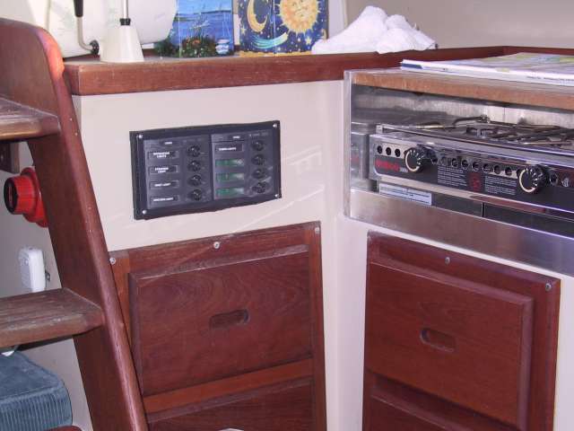
I took some photos of the original Catalina Switch panel on my Cat25 1989 and also of the BEP Switch Panel I installed just below the sink area to facilitate turning on the Nav and/or steaming lights without having to leave the cockpit area. The photos are mainly to illustrate what the panel circuitry looks like for the catalina Switch panel with one master circuit breaker and a BEP Switch Panel where each switch is a circuit breaker. The negative bus board for each panel is located nearby each panel. The positive leads from each load is directly connected to each switch in each panel. The hot side of each switch has a common positive connector/bus bar built into each panel.


Edited by - on
Go to Top of Page
  Previous Topic Topic Next Topic  
 New Topic  Topic Locked
 Printer Friendly
Jump To:
Association Forum © since 1999 Catalina Capri 25s International Association Go To Top Of Page
Powered By: Snitz Forums 2000 Version 3.4.06
Notice: The advice given on this site is based upon individual or quoted experience, yours may differ.
The Officers, Staff and members of this site only provide information based upon the concept that anyone utilizing this information does so at their own risk and holds harmless all contributors to this site.