Notice:
The advice given on this site is based upon individual or quoted experience, yours may differ.
The Officers, Staff and members of this site only provide information based upon the concept that anyone utilizing this information does so at their own risk and holds harmless all contributors to this site.
I purchased a 1981 Catalina 25 dinette about a month ago and would like to preface my question with the fact that have little knowledge of boats beyond the most basic of things and absolutely no knowledge of 12v electrical systems. With that in mind i cannot get the shore power to work on my boat I know that that the boat is getting power from the dock because the shore power cord I purchased from West Marine has a red light on the part that attaches to the boat that is supposed to indicate that electricity is getting to the boat. I tried flipping the AC main switch in the galley and had the red 1-all-2 switch on all with the main battery found in the bilge connected. I checked that all the breakers were reset and believed they were. I tried flipping the bilge and Navigation light switches along with the cabin lights non of which worked. At this point I did not know what to do which is why I am posting here any suggestions would be greatly appreciated. I will post a picture of the electrical panel later I someone borrowed my digital camera with the pictures on it.
Matt, do you have a battery charger plugged into the ac plug and attached to your battery? If your batt is depleted and not connected to charger, there would be no juice going to the nav lights etc from the shore power.
Reading your posting, it sounds like you are judging if your shore power is working by checking the nav lights, etc. So, just to make sure I have got this right, let me start with this:
The 12 Volt DC electrical circuit is completely independent of any shore power hooked up to a boat's AC circuitry. On my boat, when I hook up the shore cable to my boat's shore connection (which is located inside the port coaming in the cockpit), that enables the 2 AC outlets in my cabin to be used for AC loads. One outlet is behind the sink and my other outlet is on the aft end of the starboard seatback. I have an AC panel under the steps that consists of one circuitbreaker. I can check if my AC outlets are working by simply plugging an AC appliance, etc into the outlet.
My 12 volt DC system works all my boat lights, fishfinder, VHF, fans and provides starting power for my outboard. I have 2 12 volt batteries to run the DC loads and they are connected via the 1-both-2 (DC) battery switch.
While I started off above stating that the AC and 12 volts systems are independent of each other, well that is not completely true if a battery charger is installed onboard. I have a battery charger permanently hooked up behind the AC outlet located on the starboard side. When I have shore power, the battery charger automatically comes on and the DC wire leads from it are hooked up to each of my batteries. Not to complicate things but when I do not have shore power, my batteries can also be recharged from the solar panel I have that is also hooked up to the batteries.
Some things to check: if you have fault protected AC outlets, make sure the button has been pushed in to enable the outlets. If you have an AC appliance, etc plugged into one of the AC outlets and still cannot get it to work, then ensure the AC circuitbreaker is on. For the DC circuit, you indicated that you know the battery is good. Make sure the main circuit breaker on the DC panel is pushed in or if it has switch circuitbreakers, that the circuitbreakers are on. If your panel has fuses ?? well then you have to check that you have no fuses blown. Next if you still are having problems is to check individual circuits with a voltmeter to see if you are getting any juice thru the wires.
Two things to be aware of... One is that you really need to be careful not to cross wire the 120volt AC shore power to the 12volt DC ship power. These do not mix well at all. With your vintage boat, the 120volt AC shore power is probably provided with a black and a white wire. The black is the "hot" side; the white is the "ground" side. With the 12volt DC ship power you probably see red wires and black wires. Here the red is the "hot" side and the black wire is the "ground" side. So, be careful NOT to connect black wires together unless you know for sure that you are not crossing 120volt AC with the 12volt DC circuits.
Second, if you have checked the battery and the fuses, and have found both okay - but the lights et al still don't work; there's a good chance that there is corrosion on the spade terminals and/or the buss bars. It's easy to clean these and often corrects the problem.
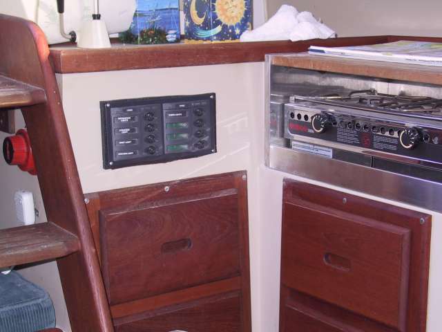
And, here's a link to the tech tips section that shows the electrical panel upgrade that I've made to Snickerdoodle. Since the photo I've also wired in a volt meter to the ship power circuits.
Larry, I was (incorrectly) judging the shore power by the the nav lights i did not try the ac plugs in the cabin. I am going to try that out the next time i go out to the boat. and to be clear i do have a battery charger hooked up to the electrical system. i have a picture but i cannot figure out how to post it sorry new to the forum world.
<blockquote id="quote"><font size="1" face="Verdana, Arial, Helvetica" id="quote">quote:<hr height="1" noshade id="quote"><i>Originally posted by mpc86</i> <br />...small sorry for the repeated posts<hr height="1" noshade id="quote"></font id="quote"></blockquote id="quote">Hi Mathew... You can edit your post by clicking the button in its header.
<blockquote id="quote"><font size="1" face="Verdana, Arial, Helvetica" id="quote">quote:<hr height="1" noshade id="quote">it is worth noting a couple of the fuses won't stay in not sure what to do about that either<hr height="1" noshade id="quote"></font id="quote"></blockquote id="quote">
You can buy replacement fuse fixtures for the panel. Do a search online. The panel is made by Sea Dog. Here is a link to one source. I am sure there are others.
Larry do you have a picture of your Charger setup?
Thanks
-eddy
<blockquote id="quote"><font size="1" face="Verdana, Arial, Helvetica" id="quote">quote:<hr height="1" noshade id="quote"><i>Originally posted by OLarryR</i> <br />Reading your posting, it sounds like you are judging if your shore power is working by checking the nav lights, etc. So, just to make sure I have got this right, let me start with this:
The 12 Volt DC electrical circuit is completely independent of any shore power hooked up to a boat's AC circuitry. On my boat, when I hook up the shore cable to my boat's shore connection (which is located inside the port coaming in the cockpit), that enables the 2 AC outlets in my cabin to be used for AC loads. One outlet is behind the sink and my other outlet is on the aft end of the starboard seatback. I have an AC panel under the steps that consists of one circuitbreaker. I can check if my AC outlets are working by simply plugging an AC appliance, etc into the outlet.
My 12 volt DC system works all my boat lights, fishfinder, VHF, fans and provides starting power for my outboard. I have 2 12 volt batteries to run the DC loads and they are connected via the 1-both-2 (DC) battery switch.
While I started off above stating that the AC and 12 volts systems are independent of each other, well that is not completely true if a battery charger is installed onboard. I have a battery charger permanently hooked up behind the AC outlet located on the starboard side. When I have shore power, the battery charger automatically comes on and the DC wire leads from it are hooked up to each of my batteries. Not to complicate things but when I do not have shore power, my batteries can also be recharged from the solar panel I have that is also hooked up to the batteries.
Some things to check: if you have fault protected AC outlets, make sure the button has been pushed in to enable the outlets. If you have an AC appliance, etc plugged into one of the AC outlets and still cannot get it to work, then ensure the AC circuitbreaker is on. For the DC circuit, you indicated that you know the battery is good. Make sure the main circuit breaker on the DC panel is pushed in or if it has switch circuitbreakers, that the circuitbreakers are on. If your panel has fuses ?? well then you have to check that you have no fuses blown. Next if you still are having problems is to check individual circuits with a voltmeter to see if you are getting any juice thru the wires. <hr height="1" noshade id="quote"></font id="quote"></blockquote id="quote">
<br />Take a voltmeter with you to the boat. Turn off everything on the switch panel and the battery switch. Check the battery voltage. Turn on the on/off or 1/all/2/off battery switch. All of the following voltages should be the same as the battery voltage and the readings are taken on the back of the switch panel. Read from the battery side of the main power switch to DC ground for battery voltage. Turn on all switches if you are alone; if somebody is helping you, you can have them turn on switches individually as you are ready to check them. Main on and check the distribution side of the Mains to ground. Leave the Main on and check the Main side of the switches to ground. With subsequent switches on, check the distribution side of each switch to ground. Any system that is working should be close to battery. Any circuit that reads low or 0 either has a faulty switch, corrosion or wire failure. This will find the fault or eliminate the initial distribution system as a culprit. A $10 voltmeter is adequate for these checks. Buy a good book on 12V boat electrical systems. Don't mess with the shorepower system with the boat in the water unless you are experienced.
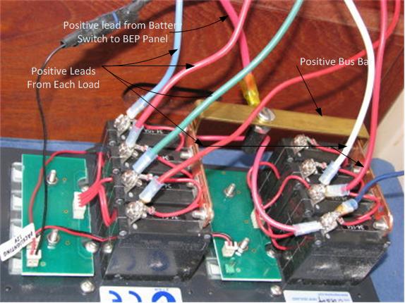
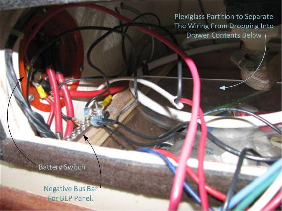
I do not have a schematic or a photo of my charger hookup but I have a photo of the charger and can describe what is behind the wall it is mounted to and it is not a complex setup. My charger can charge either battery independently since it has two leads for each battery. I have those leads directly connected to the positive and negative terminals of each battery. Each positive lead has an in-line fuse. The chargeer gets it's juice permanently hooked up with wires leading under the seat to the back of the AC outlet I have located on the aft end of the starboard seatback wall. So...when the AC outlet has juice, the charger automatically comes on. Just for jollies, I also included a photo of the insides workings of my new DC Switch Panel installed in front and under the sink.
Larry, In your pic showing the breaker panel under the sink (nice job, btw) it looks like there is a black spacer of some sort between the panel and the fiberglass. What is that?
The black spacer, I believe you are talking about the black dense foam that is actually on the whole perimeter of the opening is probably not necessary but I used it as sort of a gasket to then mount the panel to the fiberglass wall. There are screw holes that are thru the gasket into the fiberglass and when I attach the screws to the panel, the panel sits flush up against the gasket material. What you cannot see the pictures is that the inner frame of the breaker panel comes fairly close to the underside of the sink. On the sink bottom, I have heavy duty black insulated tape that covers the aluminum sink bottom where the inner breaker panel comes close to it. The dense foam gasket on the outsideholds the panel about 1/8" - 1/4" off the fiberglass wall but even without the gasket, the breaker panel will not touch the aluminum sinkbottom...but closer to it.
Besides having a new panel that has more switches than the original, I specifically mounted the panel on the sink wall because from that location, the nav and steam lights are accessible from the cockpit. Otherwise, the original anel under the seat steps is a pain requiring one to leave the cockpit and fish for the switches to turn the nav and/or steam lights on. Even when someone is sailing with me, not being familiar with the panel one woud oftentimes have to use a flashlight to determine which switches to turn on once in the cabin and kneeling down to turn on the switches. The new panel solves that issue !
The 8 switch-circuit breaker panel from BEP that I purchased was a bit pricey. BEP is a New Zealand Company and I purchased it many years ago thru Boaters World (USA). (Link to BEP and the switch panel below). There are other options that are less expensive, however, when I did my research the BEP panel was what I was looking for and specifically because it's inner depth behind the panel was a bit shorter than other panels I was considering. I was concerned with the inner depth because I wanted to ensure there was no interference fit with the sink bottom. However, if one were to mount the panel perhaps 1/4" lower on the sink fiberglass wall and the panel height dimension was not any larger than the BEP Panel, then another Mfr's panel would also fit. Anyone considering similar mod would be best to scrutinize the box dimension of the panels being considered to ensure there is clearance to mount the panel face on the sink wall and also have adequate clearance from obstructions behind the sink wall. http://bepmarine.com/home-mainmenu-8/product-525/901h-8-way-circuit-breaker-panel
Notice: The advice given on this site is based upon individual or quoted experience, yours may differ. The Officers, Staff and members of this site only provide information based upon the concept that anyone utilizing this information does so at their own risk and holds harmless all contributors to this site.