Catalina - Capri - 25s International Assocaition Logo(2006)  
Assn Members Area · Join
Association Forum
Association Forum
Home | Profile | Register | Active Topics | Forum Users | Search | FAQ
Username:
Password:
Save Password
Forgot your Password?

 All Forums
 Catalina/Capri 25/250 Sailor's Forums
 Catalina 25 Specific Forum
 Electrical Panel Refit
 New Topic  Topic Locked
 Printer Friendly
Author Previous Topic Topic Next Topic  

bjoye
Navigator

Member Avatar

USA
105 Posts

Initially Posted - 04/17/2017 :  10:55:18  Show Profile
These posts are an update to the initial post I made last winter. I’m a EE by training but new to marine electronics. That makes me a semi-clueless user and barely buzz word compliant. I’ve learned so much by reading previous posts here and at Sailboat Owners. Many thanks to all. And finally, Maine Sail’s site has been invaluable http://www.pbase.com/mainecruising/boat_projects. Wish I had found the site before I started the design process.

Like all projects this started as a simple 2 day project to add a functioning log meter and depth finder. The boat is a 89’ Cat 25 SR/WK. Its been owned by the family for just a few years, but was in need of some serious work. At purchase, it has no functioning AC or DC. The original plan was to just replace the old DC and AC panels with like panels from CD. On the 89’, the panels are located under the steps at floor level and the battery switch under the stairs. Over the years, water, dirt, and POs had ruined the panels and wiring beyond use. The AC circuits were a fire trap, the DC non functional. In addition, POs had added DC circuits by cutting into the panel and fiberglass backing.


After making a list of all the devices I wanted to support, I decided to re-locate the battery switch, AC and DC panels to behind the sink in the galley, the factory location of previous years. On the panel I wanted the battery switch, DC circuits breakers, DC volt meter, AC master breaker, AC circuit breaks, bilge pump switches, and a USB socket.

In addition, I wanted a battery charger and ACR to manage the house and start batteries. The plan was to locate the charger and all fuses under the steps. All wiring and the negative bus would be hidden in the thin space between under the back of the sink.

After much study I realized there was just not enough room. No only was working under the sink next to impossible, but there was not enough room to mount the battery fuses and bus directly to the battery. And finally, at the last minute, I wanted to add an inverter to the mix.

So, the third and final plan relocated the battery charger, the negative bus, and the 2 positive buses to a panel mounted on the back side of the battery box. I believe I first saw this idea here in these forums. There was just enough room on the panel for the buses, fuses, outlet and charger. Also the number of wires from the AC and DC panels thru the bulkhead is kept to a minimum. Fuses for the battery charger and bilge pumps are easily accessed. This left room to mount a inverter under the steps, with easy access to the cabin.

All of my supplies and tools came from Defender and Amazon (with a few exceptions, WM). Amazon worked out well since I could order a few lugs or connectors at a time as needed with 2 day free shipping, no minimum. Defender has a $25 min order, $12 shipping, and no sales tax. WM was needed when I ran short of supplies and really needed that lug or wire right now.

"Frayed Knot" 1989 C-25 WK/SR #5878

sethp001
Mainsheet C-25 Tech Editor

Members Avatar

814 Posts

Response Posted - 04/17/2017 :  16:46:54  Show Profile
Nice work, Bill! Nice choices on components too!


Seth
"Outlier" 1987 Catalina 25 SR/SK/Traditional Interior #5541
"Zoo" 1977 Morgan Out Island 30
"Nomad" 1980 Prindle 16
"Lost" 1988 Catalina Capri 14.2 (sold - yay!)
"Marine Tex 1" Unknown Origin POS 8' Fiberglass Dinghy
https://whichsailboat.com/2014/07/27/catalina-25-review/
Go to Top of Page

exf4gib
1st Mate

Members Avatar

USA
42 Posts

Response Posted - 05/04/2017 :  20:46:09  Show Profile
I'll be rewiring the DC on an 85 C-25 TR and am finding bjoye's write ups very helpful. I'm replacing ALL the existing wiring with Type 3 USCG/ABYC approved wire and connectors, with Ancor wire & connectors. Also replacing all legacy fixtures with LED-equipped ones. Question I have is; where some wiring was installed before the deck/hull sections were "mated", ie., buried inside the deck section, has anyone used wire "channels" to run wiring along the cabin walls? I understand the use of channels in a marine environment can be problematic as water can collect inside them. I cannot think of another way to run wire across the cabin mid-line without "hiding" them somehow. I'm also planning on relocating the DC switch panel above the starboard settee, at the aft end of the narrow shelf above the back cushion (in a wood-faced panel well-off the external cabin wall). That gets the panel away from the galley sink and also significantly shortens the wiring to/from the battery "locker".

Arnie W.
85 C-25 TR/FK #4747 "Lifted"
Go to Top of Page

OLarryR
Master Marine Consultant

Members Avatar

USA
3367 Posts

Response Posted - 05/05/2017 :  04:20:05  Show Profile  Visit OLarryR's Homepage
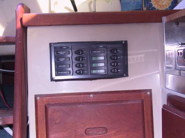
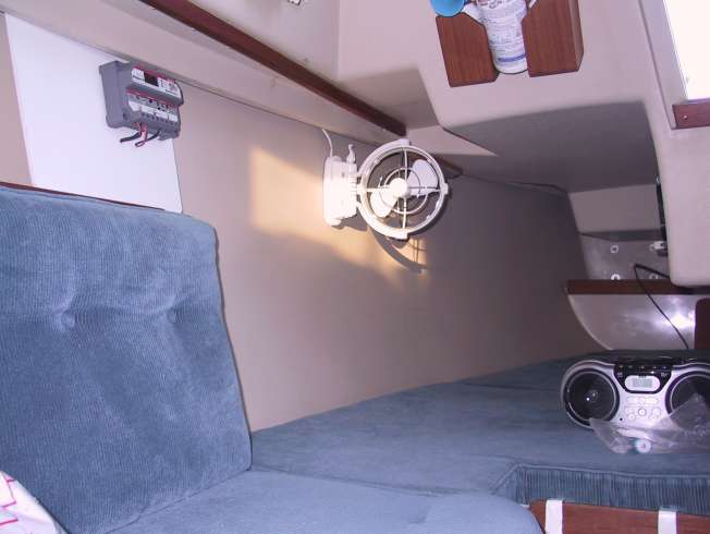
I added an addl switch panel to the flat section just below and in front of the galley sink. I placed it in that location for easy access from the cockpit to turn on the nav and/or steaming lights. All mast wiring to the old panel was replaced and wired to the new panel. 2 fans were mounted, one on top of cabin mast column bulkhead and also in the quarter berth area. I replaced both my AC outlets with ground fault outlets and hooked in a Guest 2 battery bank AC/DC charger into the circuit between one of the AC outlets and outputs run independently to each battery. I have 2 DC outlet plugs, one below the steps which was exsting and then added one toward forward end of starboard main cabin seating. Most (but not all) wiring to the old panel was moved to the new 8 switch DC panel installed. I also have a 20 watt solar panel for recharging my 2 batteries. Link to my electrical work and a couple of photos, below.
http://catalina25.homestead.com/BattPanel.html


Larry
'89 Robin's Nest#5820, Potomac River/Quantico, Va
http://catalina25.homestead.com/olarryr.html
Go to Top of Page

bjoye
Navigator

Members Avatar

USA
105 Posts

Response Posted - 05/05/2017 :  11:40:16  Show Profile
On the 89', I found plenty of room for multiple runs of cables along edge of the cabin ceiling meets the outer hull, where the original wires were run. There is a thin gap between the ceiling and the outer hull, just wide enough to run your fingers and to push one or two cables thru. Plenty of room on the other side. The original electrical wires were secured with zip ties screwed. On the port side, this channel runs from the bow into the cockpit dumpster. On the starboard side, from the bow into the aft berth. I used an electricians fish tape to make the runs. It did help that I completely removed the original wiring, as it would interfere with running new lines.

"Frayed Knot" 1989 C-25 WK/SR #5878
Go to Top of Page

exf4gib
1st Mate

Members Avatar

USA
42 Posts

Response Posted - 05/07/2017 :  13:10:29  Show Profile
Larry, sweet looking "mod" job! Bill, thanks for your explanation! Those screws securing the wire clips will be tough to get to. The outboard teak trim pieces may need to be removed to provide better access - ???

Arnie W.
85 C-25 TR/FK #4747 "Lifted"
Go to Top of Page
  Previous Topic Topic Next Topic  
 New Topic  Topic Locked
 Printer Friendly
Jump To:
Association Forum © since 1999 Catalina Capri 25s International Association Go To Top Of Page
Powered By: Snitz Forums 2000 Version 3.4.06
Notice: The advice given on this site is based upon individual or quoted experience, yours may differ.
The Officers, Staff and members of this site only provide information based upon the concept that anyone utilizing this information does so at their own risk and holds harmless all contributors to this site.