Catalina - Capri - 25s International Assocaition Logo(2006)  
Assn Members Area · Join
Association Forum
Association Forum
Home | Profile | Register | Active Topics | Forum Users | Search | FAQ
Username:
Password:
Save Password
Forgot your Password?

 All Forums
 Catalina/Capri 25/250 Sailor's Forums
 Catalina 25 Specific Forum
 Mast raising system
 New Topic  Topic Locked
 Printer Friendly
Previous Page | Next Page
Author Previous Topic Topic Next Topic
Page: of 3

OJ
Master Marine Consultant

Members Avatar

USA
4382 Posts

Response Posted - 09/01/2014 :  09:47:52  Show Profile
Gin pole:


Edited by - on
Go to Top of Page

islander
Master Marine Consultant

Members Avatar

USA
3992 Posts

Response Posted - 09/01/2014 :  12:55:56  Show Profile
Oh sure, Let me just run out to my machine shop and whip one of those out!

Edited by - on
Go to Top of Page

OJ
Master Marine Consultant

Members Avatar

USA
4382 Posts

Response Posted - 09/01/2014 :  16:46:58  Show Profile
quote:
Originally posted by islander

Oh sure, Let me just run out to my machine shop and whip one of those out!


Wait! Let me mail the cardboard prototype to you first!

All the measuring and thinking that has gone into this stupid thing and we still have to walk the (tall rig) mast up quite some ways before the block and tackle can take over!


Edited by - OJ on 09/01/2014 16:51:51
Go to Top of Page

JohnP
Master Marine Consultant

Members Avatar

1519 Posts

Response Posted - 09/02/2014 :  11:09:42  Show Profile
I agree with everyone's comments above.

I made an A-frame out of 2 x 4's exactly like Scott's photo above, but since I rarely use the A-frame, I attached the base of each leg simply by tying a 3/8 inch line or a piece of strong wire cable throught the A-frame hole at the bottom and through the chainplate. That allows easy rotation and needsno special fitting to the chainplate.

You asked about the size of the legs. Yo proabably did not mean the size of the "feet". For legs, I used 12 foot 2 x 4's, and OJ's cadillac version uses 9 foot conduit sections.

There is little difference with different leg lengths for a standard rig mast (~28 feet in height) with no furler. If you are dropping and raising a mast with a furled jib still in place, there is considerably more weight to hold up, and longer legs provide a little more leverage and stability down to an angle of 45 degrees.

For a tall rig mast you may want longer A-frame legs, and with the weight of a furler and jib particularly.

Below 45 degrees, I found that this setup that drops the A-frame with the mast kept the mast well under control, and even with some sideways breeze it was easy and safe to continue lowering the mast slowly and catching it in the cockpit with one hand while feeding more line to the A-frame turning block on the bow.

I learned that my 28 foot mast weighs something like 75 pounds and is easy to guide into the crutch that I simply attach by tying with lines to the pushpit.

I've only done this single-handed, but having a helper or two hold the mast centered and then guide it into the crutch would make the process very straightforward.

Edited by - on
Go to Top of Page

redeye
Master Marine Consultant

Members Avatar

3474 Posts

Response Posted - 09/02/2014 :  11:09:49  Show Profile
I made an "A" frame one out of wood that folds up to fit in my Honda civic. I've only used it once. I'll drag it out and get some shots of it.


Edited by - on
Go to Top of Page

kiko
1st Mate

Members Avatar

USA
69 Posts

Response Posted - 09/02/2014 :  17:47:18  Show Profile  Visit kiko's Homepage
I just made the A-frame utilizng Davey J's examples. I must have screwed up something as I am bending the bolts I use to secure the a frame pipe to the pipe nipples at the chainplate. while testing the arc, it binds up and bends the bolts at around 40 degrees.

Edited by - on
Go to Top of Page

GaryB
Master Marine Consultant

Members Avatar

USA
4275 Posts

Response Posted - 09/02/2014 :  21:02:19  Show Profile
Sounds like your holes are drilled 90 degrees apart (top to bottom) and they should have been drilled to line up with the holes in the chain plates which is not quite 90 degrees from the holes at the top of the nipple.

Slide the nipple down over the chain plate and line up the holes at the bottom of the nipple with the holes in the chain plate. Then standing directly above the nipple look down and see how the holes in the top of the nipple line up with the holes in the conduit. I'm betting you will see that they should have been drilled at a different angle so they would line up with the holes in the conduit. If they are at the proper angle there should be almost no binding. Definitely not enough to bend the bolts.

Edited by - GaryB on 09/02/2014 21:03:21
Go to Top of Page

kiko
1st Mate

Members Avatar

USA
69 Posts

Response Posted - 09/03/2014 :  08:15:07  Show Profile  Visit kiko's Homepage
Hey Gary, not binding there, when the frame moves thru it's arc, it is wanting to twist the pipe nipple arrangement. The nipples are secure with the holes on the chainplate.

Edited by - on
Go to Top of Page

Davy J
Master Marine Consultant

Members Avatar

USA
1511 Posts

Response Posted - 09/03/2014 :  08:33:08  Show Profile
Can you take and post some photos of what you have constructed?

My first thought is that the holes are, maybe, too far away from each other. And as Gary said, maybe aligned incorrectly.

Photos would help.

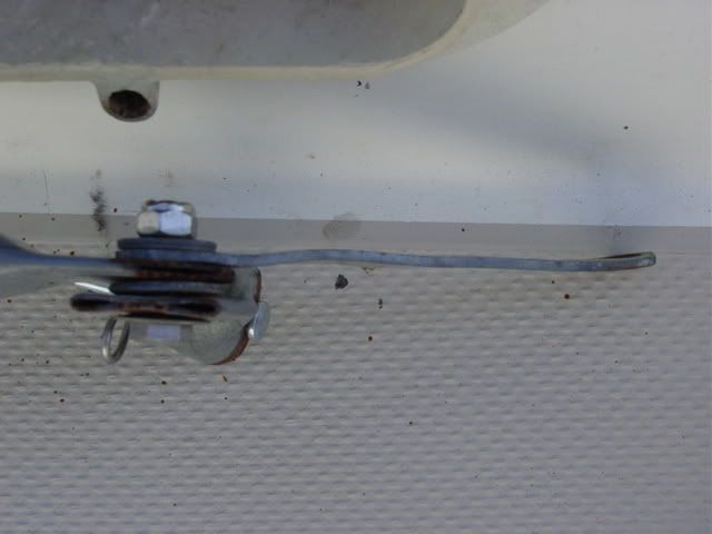
Look at this photo and you will see that the clevis pin is not all the way to 90 degrees, in relation to the hinge bolt:


Voyager pointed that out as well, on the bottom of the first page.


Edited by - Davy J on 09/03/2014 08:41:11
Go to Top of Page

islander
Master Marine Consultant

Members Avatar

USA
3992 Posts

Response Posted - 09/03/2014 :  11:54:54  Show Profile
The best way to get the angles right is to first drill the holes for the pipe nipple to the chainplate. Now Bolt the nipple to the chainplate. Now lay the A frame out on the deck exactly like its suppose to be when it if fully built. Put the leg of the A frame against the pipe nipple and drill the hinge hole through the nipple and the leg keeping the drill 90 deg to the leg, If you do this correctly (90deg to the leg) that hinge bolt should angle slightly toward the back of the boat.

Edited by - on
Go to Top of Page

kiko
1st Mate

Members Avatar

USA
69 Posts

Response Posted - 09/03/2014 :  12:43:49  Show Profile  Visit kiko's Homepage
Hey Davy J and Islander, one thing I noticed is I did not flatten the pipe where it joins the pipe nipple.

Will try that first and then will make new pipe nipples and redrill the way islander explained.

Thanks guys, will let you know if I have any success :)

Edited by - on
Go to Top of Page

islander
Master Marine Consultant

Members Avatar

USA
3992 Posts

Response Posted - 09/03/2014 :  16:34:39  Show Profile
Also when you bolt it all together don't make the bolts too tight in the hinge joint. Finger tight will do. This will leave some play in the A Frame and will reduce any binding that might occur.

Edited by - on
Go to Top of Page

kiko
1st Mate

Members Avatar

USA
69 Posts

Response Posted - 09/03/2014 :  18:52:16  Show Profile  Visit kiko's Homepage
Are the forward lower chainplates supposed to turn? No nylocks down below for them.

Edited by - on
Go to Top of Page

GaryB
Master Marine Consultant

Members Avatar

USA
4275 Posts

Response Posted - 09/03/2014 :  20:09:56  Show Profile
Nope! If they are turning water is getting into the core every time it rains. That needs to be repaired ASAP.

Edited by - on
Go to Top of Page

kiko
1st Mate

Members Avatar

USA
69 Posts

Response Posted - 09/03/2014 :  20:48:59  Show Profile  Visit kiko's Homepage
No wonder my a frame project is having issues. So nylocks and rebed them along with repoxying hole?

Edited by - on
Go to Top of Page

kiko
1st Mate

Members Avatar

USA
69 Posts

Response Posted - 09/03/2014 :  20:52:06  Show Profile  Visit kiko's Homepage
And I f I rebed them cause all four turn.. What angle should they be at? Meaning looking down at it..what angle show they be at?

Edited by - on
Go to Top of Page

Dave5041
Former Mainsheet Editor

Members Avatar

USA
3754 Posts

Response Posted - 09/03/2014 :  21:00:59  Show Profile
Perpendicular to a plane through the particular shroud and the mast. Run a line from the mast to the chainplate and set the cp perpendicular to it. It isn't that critical.

Edited by - on
Go to Top of Page

islander
Master Marine Consultant

Members Avatar

USA
3992 Posts

Response Posted - 09/04/2014 :  14:34:29  Show Profile
Here's a photo so you can see how they face. There should be 2 screws in the deck flange that keeps them from rotating You can see them in the photo, And a Aluminum backing plate on the interior of the boat.

Aluminum backing plate above the shelf

Edited by - islander on 09/04/2014 14:42:32
Go to Top of Page

Dave5041
Former Mainsheet Editor

Members Avatar

USA
3754 Posts

Response Posted - 09/04/2014 :  17:21:02  Show Profile
Interesting, mine are about 90º to yours and were presumably built that way since there are only two screw holes underneath. I don't see any reason for concern since they load a single, centered stud The shrouds are angled in two planes and the cp.'s cannot align perfectly to both. Close enough, they don't appear to have weakened the deck or pulled through in 35 years.

Edited by - on
Go to Top of Page

kiko
1st Mate

Members Avatar

USA
69 Posts

Response Posted - 09/04/2014 :  18:40:13  Show Profile  Visit kiko's Homepage
I don't have any screw holes on my plates at all...

Edited by - on
Go to Top of Page

islander
Master Marine Consultant

Members Avatar

USA
3992 Posts

Response Posted - 09/05/2014 :  05:51:47  Show Profile
Your boat is a 78 so I just looked at the chainplates from CD. Seems that the early boats used a 3/8" chainplate and changed them to a better/larger 1/2" design later on. You could have these early chainplates that possibly didn't have the screw holes. Good time to upgrade?http://www.catalinadirect.com/index.cfm/product/37_39/chainplate-eyebolt-retrofit-kit-for-c-25-c-27.cfm
quote:
Interesting, mine are about 90º to yours and were presumably built that way since there are only two screw holes underneath.

Thats strange... Seems that the chainplate is vertical and the shroud is angled. Your set up would put all of the load/tension on the outside of the toggle no?

Edited by - islander on 09/05/2014 08:01:10
Go to Top of Page

Voyager
Master Marine Consultant

Members Avatar

USA
5231 Posts

Response Posted - 09/05/2014 :  06:51:36  Show Profile
OT alert ...
Scott
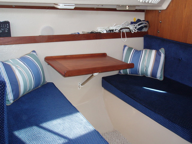
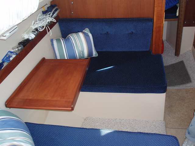
It's great what you did with the dinette - got rid of that big old table board and put in a shelf. Looks much more comfortable.

Edited by - Voyager on 09/05/2014 06:52:27
Go to Top of Page

islander
Master Marine Consultant

Members Avatar

USA
3992 Posts

Response Posted - 09/05/2014 :  07:06:26  Show Profile
Thanks Bruce, That is actually a bread board I found in a store and re- worked it a bit. It opened up the interior and is still big enough to put a cold one on or dinner for two. I still have the big table down in the basement so the next owner will have 2 tables to choose from.

Edited by - on
Go to Top of Page

Dave5041
Former Mainsheet Editor

Members Avatar

USA
3754 Posts

Response Posted - 09/05/2014 :  10:59:30  Show Profile
Scott, not all the load, just a little more.

Edited by - Dave5041 on 09/05/2014 11:05:55
Go to Top of Page

britinusa
Web Editor

Members Avatar

USA
5404 Posts

Response Posted - 09/05/2014 :  11:32:10  Show Profile  Visit britinusa's Homepage
Scratching my head about the vectors in OJ's rig and thinking that most of the force at the top of the mast when raising is directed at the mast foot!

Moving the attachment from the mast head to just below the spreaders would change that considerably ... wouldn't it?

ie. moving the attachment to just below the spreaders would move the direction of the lifting vector.

Paul

Edited by - on
Go to Top of Page
Page: of 3 Previous Topic Topic Next Topic  
Previous Page | Next Page
 New Topic  Topic Locked
 Printer Friendly
Jump To:
Association Forum © since 1999 Catalina Capri 25s International Association Go To Top Of Page
Powered By: Snitz Forums 2000 Version 3.4.06
Notice: The advice given on this site is based upon individual or quoted experience, yours may differ.
The Officers, Staff and members of this site only provide information based upon the concept that anyone utilizing this information does so at their own risk and holds harmless all contributors to this site.