Notice:
The advice given on this site is based upon individual or quoted experience, yours may differ.
The Officers, Staff and members of this site only provide information based upon the concept that anyone utilizing this information does so at their own risk and holds harmless all contributors to this site.
I was looking for excuses to avoid cleaning up tonight, so I started sketching the design for an improved cockpit table. I am interested in getting your comments.
The goal here is to significantly reduce its size to improve access to the V-berth, but still preserve the ability to fold it out into a sizeable space for dining, opening charts, etc. I hope to fabricate this sometime this winter, but I'll have to see what other projects I need to do around the house (and how much I want to procrastinate on them ).
I think this is an improvement over the shape and size of [url="http://pages.suddenlink.net/arlyn/sailing/cabintable.html"]Arlyn's design[/url], but it incorporates his use of 180° recessed twin pin "sewing machine" hinges to allow folding the table onto itself. In this first draft, I have designed it to be fabricated from two 2'x3' pieces of plywood. (Stores typically sell 2'x4' or 4'x8', so I would buy two 2'x4' pieces and have some waste.)
Please note that I do not have any CAD software, so I have just sketched this out using the drawing editor for Microsoft Office.
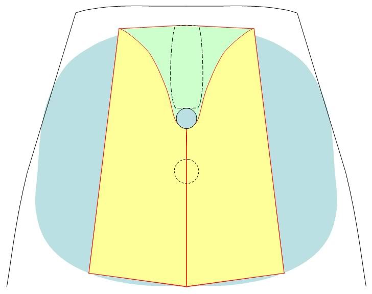
The first drawing shows what the table would look like folded up. The black outline is a rough approximation of the floor layout. The light cyan is an approximation of the current C250 table, the light green is the bottom layer of the table, and the yellow is the two folded over parts. You can also see the compression post, and an outline of the central pedestal used on late model C250WK models (different from Arlyn's boat). Note that, when folded up, there is substantial floor space to allow getting past the table to the front V-berth:
<center></center>
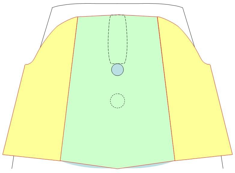
This drawing shows the table folded out. Note that it is a little bigger than the original table, and overhangs the settees by a couple of inches so you don't spill food on your shorts (don't ask why I need to worry about this! ):
<center></center>
Rick S., Swarthmore, PA PO of Take Five, 1998 Catalina 250WK #348 (relocated to Baltimore's Inner Harbor) New owner of 2001 Catalina 34MkII #1535 Breakin' Away (at Rock Hall Landing Marina)
Nice drawings Rick, here are my thoughts having built something similar.
My design uses piano hinges so that the 'leafs' fold down. The compression post position is much further fwd on JD (is yours a guestimate?)
My table leafs are rounded on all corners to prevent hip snags.
Ours has folding legs so that the table can be lowered onto thin rails that are attached to the cabin side of the seat lockers.
Now my critique of my design. 1)Too long: Although in the down position it extends the v-berth by nearly 3 feet, it could be 6" less, leaving more room in the cabin.
2)Too awkward to raise and lower. I have 4 legs that are pivoted on the underside of the fixed center part of the table. They are long enough to ensure the table is a comfortable height when raised, and short enough to ensure there is room for them to swing up in the lowered position.
3)Too wide: barely, but it's a bit awkward getting to the sat down position without bumping the table.
One advantage of my design is that the whole table can be swiveled around the compression post by about 25degrees making more room in the cabin when you need to get into the lockers.
Henk has a neat design. Does not extend the v-berth, but does keep things slim when the leafs are out of the way.
I'm working on a total redesign too, but your sketch is further along than my thoughts so far.
We've used this functional, swing-up, slide-out table for some years and like it very much. The slide-out sections allow breakfast, lunch, snacks and dinner to be consumed in a comfortable position. The swing-up section will provide the dinner table with more room for dishes, pots and pans. The swing-up section is removable and can double as a serving tray. Slide-out sections are also used as a base for the lap-top, writing letters, etc.
<blockquote id="quote"><font size="1" face="Verdana, Arial, Helvetica" id="quote">quote:<hr height="1" noshade id="quote"><i>Originally posted by britinusa</i> <br />...The compression post position is much further fwd on JD (is yours a guestimate?)...<hr height="1" noshade id="quote"></font id="quote"></blockquote id="quote"> No, my drawing is based on actual measurements. The "jigsaw puzzle" cutout on the original table is exactly 10" long, as it is on the proposed new table. I also went to the boat yesterday and measured the front of the compression post at 11.5" from the fiberglass bulkhead at the floor. Since my floor is lower than yours, and the bulkhead may be slanted from top to bottom, that measurement may be a little different on a 250WB.
One thing that I did not show is that my cushions all overhang the fiberglass by about 2", which can make a significant difference in perception of the size of the table and location of the compression post.
My design will not pivot if I stick with the pedestal mount that Catalina supplied for my boat.
I have no desire to move this table into the cockpit, since I already have a cockpit table that I'm happy with.
Drop-down leaves offer the advantage of much more readily available hardware that handles the stresses better, but I would prefer to have the open space to put my leg under the table. In fact, the table will be used in the closed position 99% of the time - we eat inside the boat very infrequently, but I want to preserve the ability to do this in my design.
By the way, this draft of the design is meant to show the largest size possible with 2' wide plywood. The base table (green part) is exactly 2' wide at its widest point. Making the base table and accompanying leaves narrower will further improve access, as well as reducing the moment arm that increases the stress at the point where the leaves contact the base table and on the screws holding the hinges in place. I could also reduce this stress by putting rotating or sliding support arms under the table, but this would limit my ability to add fiddles to the underside of the leaves.
I could also shorten the table to increase cabin space, but I'm somewhat limited there because of the need to keep the table's center of mass close to the pedestal.
I have a lot to think about, but wanted to get a first design down to help visualize it. I'll probably also make some changes to ease fabrication, such as making the very front and rear edges straight. Rounding the corners might be nice, but could complicate fabrication using plywood and my crude wood tools. I also want very much for the leaves to match up with the base table so I have a smooth surface with very narrow seam when the (yellow) leaves are folded over the (green) table, since that is how the thing will be used 99% of the time.
My next step, when I get around to it, will probably be to construct a cardboard mock-up of the whole thing. I saved the box from a big screen TV to do this.
The other plywood project that I need to work on is a new V-berth cover. For whatever reason, mine is cut into two pieces with a front and back half. It would be much more accessible if it was split into left and right sides to correspond to the V-berth covers, so I could just open up one side of it.
Rick, ackowledged, the Wing keel cabin layout is different, I'm surprised that the compression post seems so far fwd in your pic.
The rounded aft edges of our table are a major issue, if they were sharp corners, we would be gouged every trip
I'm 6' and Peggy is 5'6" and it's me that has the issue with the closeness of the outboard edge of the table making it tough to get into the seated position.
Is there any chance you could use a two part support post that could have something like a bayonet fitting that would allow twisting it and thus lowering the table to use as a v-berth extender? Or is that not in your game plan?
I cut our v-berth cover fore & aft and connected the two pieces with a stainless piano hinge, totally agree with you on that concept, works great.
Henk, your table rocks! Sadly we need the v-berth extender, so your design would not work for us. However, if we made the central part of the table really narrow, then it would. So I'm considering that concept.
Let's know how your project progresses Rick. FYI, I used iron on banding to seal the edges of the plywood that I used for our table, worked really well and we have had no issues with that part of it.
Thanks for your comments and suggestions. There are some really good ones, which is why I posted this for comments.
<blockquote id="quote"><font size="1" face="Verdana, Arial, Helvetica" id="quote">quote:<hr height="1" noshade id="quote"><i>Originally posted by britinusa</i> <br />...The rounded aft edges of our table are a major issue, if they were sharp corners, we would be gouged every trip ...<hr height="1" noshade id="quote"></font id="quote"></blockquote id="quote"> I'll have to think about this. It seems everyone does rounded corners, so there must be a reason. <blockquote id="quote"><font size="1" face="Verdana, Arial, Helvetica" id="quote">quote:<hr height="1" noshade id="quote"><i>Originally posted by britinusa</i> <br />...Is there any chance you could use a two part support post that could have something like a bayonet fitting that would allow twisting it and thus lowering the table to use as a v-berth extender? Or is that not in your game plan?...<hr height="1" noshade id="quote"></font id="quote"></blockquote id="quote"> I had not planned to do any v-berth extension. The pedestal mount would not seem to be quite as secure for this as your lowered coffee table. A bayonet fitting might be overly complicated, BUT a second, shorter tube should be quite simple if I can come up one that's the right diameter.
I'll have to go back and have a look at the fiberglass settees. If I'm going to go to all this trouble to fab a new table, maybe I should size it to work as a v-berth extension just in case my needs change. I wouldn't need to add the stringers to the settees right now, but by making the table the right size and shape, it might be a nice option to have for the future.
<blockquote id="quote"><font size="1" face="Verdana, Arial, Helvetica" id="quote">quote:<hr height="1" noshade id="quote"><i>Originally posted by britinusa</i> <br />...I cut our v-berth cover fore & aft and connected the two pieces with a stainless piano hinge, totally agree with you on that concept, works great...<hr height="1" noshade id="quote"></font id="quote"></blockquote id="quote"> Are you saying that your cover is cut both fore/aft and side to side? Or was your cover originally one piece, and was cut (and hinged) once by you?
Mine is two pieces, but cut in the wrong direction (in my opinion). I've assumed I'd need to make a new cover from scratch to address this, but if there was a way to splice together the current pieces and recut it the other direction, that may be easier. I just can't envision a way to do this with sufficient strength.
Our v-berth space cover was a single piece of plywood. I cut ours fore & aft so that the hinge runs down the boat centerline and each side can be folded up.
Thanks for the example on the v-berth storage cover. Since mine is already cut the wrong way I'll have to make a new one and cut it the right way. I'll probably have to buy/borrow a router to bevel the edge properly.
As for the table, today I spoke to a professional woodworker about it, and I'm awaiting a rough quote. If I were to do it myself there are multiple compromises I'd make in design (due to my limited tools and skills) and quality of materials (I'd go cheap because I'd be afraid of screwing it up and having to start over). I would prefer to have this done exactly the way I want with top grade materials. My wife and kids were having a hard time thinking of what to get me for Christmas (they were thinking of woodworking tools for this project, but I wasn't ready to lock in my choices), so instead they'll have the table made for me.
This guy built a fireplace surround for us about 8 years ago, so I know the kind of exacting quality he produces. It turns out the surround has lots of intricate engineering behind the facade to accommodate thermal expansion from the fireplace - it's a lot more complex than it appears from the outside. But that's the kind of thought the guy puts into his work. Our surround is shown on his web page:
I'd still love to avoid remaking a new v-berth cover from scratch. Do you guys think that if I put a piano hinge with lots of screws along the bottom of the existing cut that it would be strong enough to mend it? Then I could add the fore-aft cut and put piano hinges across the top:
<center></center>
Instead of a piano hinge I could possibly use a wooden firring strip to mend it, but something tells me a metal piano hinge (or perhaps a mending plate, if it could be painted for corrosion resistane) might stand up to the tensile stresses better. Brass screws would probably be too soft for this application - I'd have to use SS.
biscuits, or fir strip and glue back into one piece. The piano hinge will act as support, and the fiberglass lip on the other side supports, so you would be ok. Not nearly as strong as full plywood, but ok. At worst a backing strip for extra support as well?
I'm not clear why you have to do this. If you hinge it abeam rather than fore and aft, you've accomplished the same thing. As long as the hinge is under the cut rather than over it, you shouldn't have any risk of collapse. I think that a hinge on top will sag from the weight on the v-berth.
Since you've cut it already, just hinge it the way it is and see if it works. You haven't lost anything if it does. In fact, you'll save the cost of the other hinges. If it doesn't, then work on "Plan B"
<blockquote id="quote"><font size="1" face="Verdana, Arial, Helvetica" id="quote">quote:<hr height="1" noshade id="quote"><i>Originally posted by John Russell</i> <br />I'm not clear why you have to do this. If you hinge it abeam rather than fore and aft, you've accomplished the same thing...<hr height="1" noshade id="quote"></font id="quote"></blockquote id="quote"> Not really. I store things on the V-berth, especially anything with weight, because it helps to offset the passenger weight in the cockpit. Right now, because of the way the cover is cut, if I want to access the storage underneath, I need to clear off the whole V-berth and remove both cushions. With the cut fore-aft, I could move the stuff to one side and only have to pull up one cushion. With the fore-aft hinge on top of the cover, it's even easier.
Hinging the cover abeam accomplishes nothing, because I still need to clear both sides of the V-berth and both cushions. So my question is about whether it's possible to mend the existing cut with a hinge, mending plate, or firring strip. Then I'd do a fore-aft cut with hinge.
<blockquote id="quote"><font size="1" face="Verdana, Arial, Helvetica" id="quote">quote:<hr height="1" noshade id="quote"><i>Originally posted by John Russell</i> <br />...Since you've cut it already...<hr height="1" noshade id="quote"></font id="quote"></blockquote id="quote"> Just to make it clear, I did not cut it. It came that way. I like to think that I would have cut it in the correct direction.
<blockquote id="quote"><font size="1" face="Verdana, Arial, Helvetica" id="quote">quote:<hr height="1" noshade id="quote">biscuits, or fir strip and glue back into one piece.<hr height="1" noshade id="quote"></font id="quote"></blockquote id="quote">
1" wide by 3/16 thick fir strip grooved/glued inside the two halves with both halves glued over the full length should provide sufficient strength...
Note: before you cut in the "fore to aft", direction install (screw) the piano hinge down first and then make the cut to insure perfect alignment of the two halves.
BTW Van Heyneker Custom Woodworking, Mendenhall, PA looks like a very capable craftsman
Sorry for the naive comments/questions, but I have to ask:
<blockquote id="quote"><font size="1" face="Verdana, Arial, Helvetica" id="quote">quote:<hr height="1" noshade id="quote"><i>Originally posted by zeil</i> <br /><blockquote id="quote"><font size="1" face="Verdana, Arial, Helvetica" id="quote">quote:<hr height="1" noshade id="quote">biscuits, or fir strip and glue back into one piece.<hr height="1" noshade id="quote"></font id="quote"></blockquote id="quote">
1" wide by 3/16 thick fir strip grooved/glued inside the two halves with both halves glued over the full length should provide sufficient strength...<hr height="1" noshade id="quote"></font id="quote"></blockquote id="quote"> I don't have a tool the make a groove in the edges of the halves. Plus, it would have to be very precise, because the plywood is so thin. It sounds like it would be easier to just buy new plywood and cut a new piece. <blockquote id="quote"><font size="1" face="Verdana, Arial, Helvetica" id="quote">quote:<hr height="1" noshade id="quote"><i>Originally posted by zeil</i> <br />Note: before you cut in the "fore to aft", direction install (screw) the piano hinge down first and then make the cut to insure perfect alignment of the two halves... <hr height="1" noshade id="quote"></font id="quote"></blockquote id="quote"> Hmm, I would think that cutting in this way would create a gap that is equivalent to the thickness of the saw blade, thus creating a gap that allows some backwards rotation of the hinge. Either that, or I am misunderstanding your suggestion.
If the spliced joint proves too weak add a metal strip or... you may wish to purchase a new insert.
To make the cut use a narrow set or fine blade...
Installing the piano hinge, then removing it before cutting worked fine in our application and shows under load negligible sag. We use the V berth as our sleeping quarters for extended periods. (Last year 5 months) I'm 6 ft 210 lbs
OK, the fact that I change my mind every day is a sign that I'm not ready to start work on this yet. Here's my idea of the day:
Although I'm not crazy about drop leaves, it does offer the possibility of making a quick, relatively easy conversion of the existing table. I could slice the middle section to about 12" wide and hinge the sides with piano hinges and some commonly available hardware to support the leaves:
<center>
</center>
Since the middle section would only be 12" wide instead of 22-24" wide, it would allow much better access forward. If I wanted to put my legs under the table, I could just raise one side, and still have the other side for access to the v-berth.
I could laminate the sawed edge with white melamine "Band-It" iron-on stuff, or get some real laminate from a pro. I might even consider getting some of the large Band-It wood veneer sheets and laminating the whole table with real wood (if it can adhere to the original melamine surface).
If I end up not liking it, then I could go hire the guy to make me a new table like the one shown above.
Have any of you considered doing this with your original tables? How did it come out? Any suggestions on how to saw the melamine without chipping it?
You may wish to consider folding the side pieces up on top of the table to meet center line and around the compression post. Problem you'll see exposed hinges... Sides could be finished with imitation teak edging
We find that fiddling the table is very useful. Usual table stuff, keys, alarm clock, change, candle, notes, books, etc. can be left on the table during healing and rough weather
Cutting material... try and see if double taping the to-be-cut area will forestall splintering
When doing the Mainsheet tech section, tables were the most prolific as well as the most interesting C250 mod. I enjoyed very much seeing the various offerings to meet the needs of various owners.
In design, one first list the goals of the design. When making the list, be as expansive as possible. Then check those items believed to be rigid requirements and thereafter don't compromise them... make them happen.
Our needs vary... and a design ought to reflect those varying needs.
I don't drop in as often as I used to... but this thread on tables and other mods was a treat.
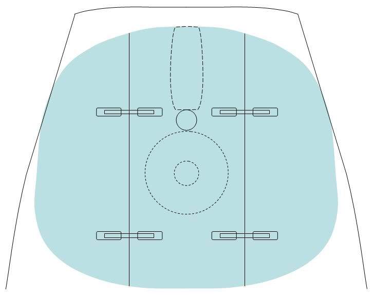
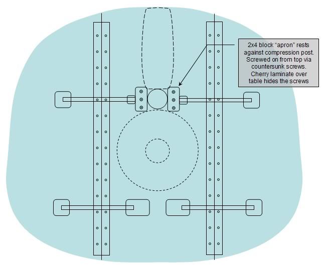
Now that the holidays are over, I've started collecting the tools, materials, and courage to chop my current cabin table into three parts, with drop leaves. Here's a drawing of my current plan:
<center></center>
The center section will be 11-13" wide. The exact width will be determined by a number of factors, including bracket dimensions and how the grain lays on the veneer that I hope to use. I will need to finish off the sawed edges of the table. Currently I plan to seal the pores with polyurethane clearcoat, and then apply the wood veneer to the edges and top, right over the existing formica. I'll probably use cherry veneer, because the teak veneer I've seen is too dark. I might consider oak, but I like the finer grain of the cherry. I'll put a few coats of clear polyurethane over the veneer to seal out moisture and provide greater resistance to chips and gouges.
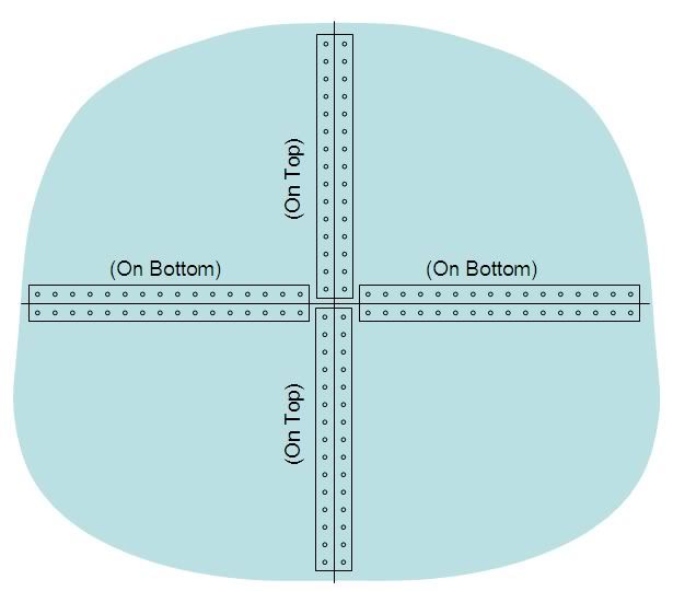
For the leaf support system, I plan to use these brackets(click pic for link):
Because the center part of the table will not have an apron, I will use the apronless version of the brackets for the aft supports (shown in the bottom of the above picture with the large descending metal bracket). However, the compression post and "jigsaw" cutaway in front of the compression post leave too little room for the large brackets there, so I got the idea to screw two 2x4 blocks under the table to act as "aprons" to support the forward brackets. Mounting the blocks snug up against the compression post gives them great rigidity against the stresses from the leaf brackets. The screw heads will be hidden by the veneer on the top surface of the table.
I found this veneer with PSA pre-applied on Amazon (click pic for link). Do any of you have a better source to recommend?
I would suggest using picket screws (or even dowels) from the bottom, inboard sides of the apron. The compression post will hide, and you will not have any issues with the table top read-through of the screws. Since the compression post will provide ample support, you can also use 1" stock for a more finished look too. Screws will move and you can end up with either a divot or raised bump...... other than that probably the most thorough plan I have ever seen....nice drawings.
We bought a cockpit table from AFI and modded it to go in the cabin. Works very well. Be aware that when you create more space to access the V-berth that you'll start banging your head on those swiveling lights that hang by the compression post!! My current project is replacing them with flush mount LED lights.
Randy - I like your table, and as you can tell from my original post, I had originally planned to do something like yours. And if the drop leaf mod does not come out well, I'll end up fabbing a new table.
We had the table completely out all last season, so we had good access to the front storage. I can't tell you how many times my wife and I banged our heads on those swiveling lights. Please post your info on the replacement lights - it will go right to the top of my list.
Ape-X - Thanks for the suggestions. My concern about screwing from the bottom was just whether the threads would have enough "grab" into the 3/4" board. Going from the top would allow much deeper threading into the wood block. But I share your concern about the potential for divots under the veneer, so I'll probably screw up from the bottom like you suggest.
I'll consider 1" finished stock, but it turns out that the dimensions are pretty critical for getting the leaf support brackets to work properly, and a 2x4 may be the perfect thickness. Also, it needs to have some strength when the compression post is not present, so that it can be removed and stored without the blocks collapsing, so a thicker block would provide more strength under those conditions.
As for the thorough plan, I get very nervous when potentially destroying original equipment, and want to make sure I've anticipated any possible "gotchas" before cutting up the table.
As an example of a "gotcha," the shape of the support brackets when folded may turn out to be critical. Here's a C28MkII with the leaf down:
<center></center>
Note how the folded bracket extends back away from the leaf. In my design, this could possibly "collide" with the compression post, preventing the leaf from falling to vertical. However, I may be able to adjust this by mounting with different thicknesses of blocks. So I had to go ahead an order the brackets tonight, since it might affect the dimensions of the center table.
Another interesting complication is the available veneer dimensions. Most veneer is available in 2' wide sheets (typically 2' x 8'). The table is 37" wide. If I cut the center part of the table to 12", my leaves would each be 13" wide (13+12+13), and since there is no way to fit 2 pieces onto the 2' wide sheet, I'll have to buy a lot of extra veneer with a bunch of waste. If I cut the center part to <11" (13.25+10.5+13.25) or >13" (11.75+13.5+11.75), then I can do two pieces with one 2' wide section, and the third piece with another section with extra leftover to make edge bands and to test different finishes. This stuff is complicated, but without planning this out I could waste a lot of money.
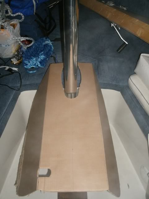
Today I made a cardboard mockup to get an idea how it would fit in the boat. Here's a pic:
<center></center>
I also hung out at the local Woodcraft store yesterday and learned a whole lot. I bought some PSA-backed edge banding in various materials to test whether it would stick to the white laminate, and to test various finishes on them. I used the bottom of the "jigsaw cutout" from my table as a test piece. The stuff sticks to the white laminate very strongly! And of the various materials, it looks like walnut provides the closest match to the wood components of my interior. So unless someone tells me that walnut is terrible in a marine environment, I'll probably go with that.
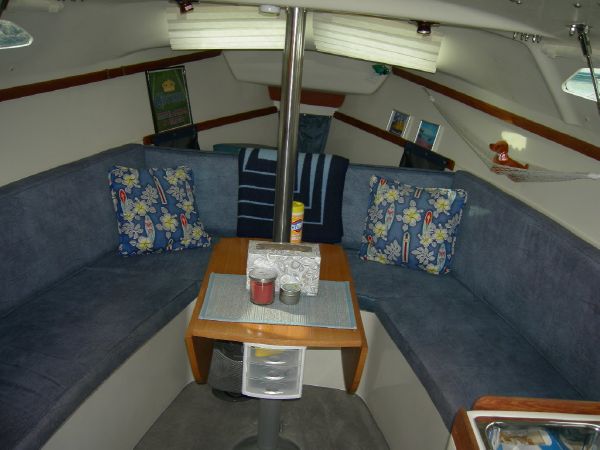
And one last picture. Here's the original C28 with leaves on both sides. This is pretty much the effect that I'm trying to create, while still having the table completely removable if needed:
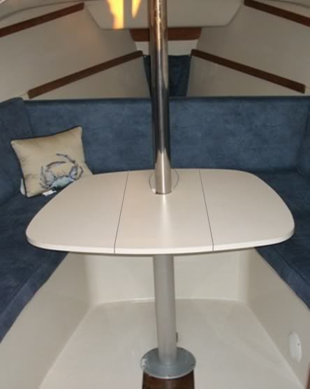
Quick update - Here's a pic of a C250 that's currently listed on Yachtworld. It looks like the owner did a similar drop leaf mod to his OEM table, although his central table is wider than I plan to do. I wonder if the guy was member here:
<center></center>
These pictures got me to thinking. Most of them (C28's and this C250 shown above) seem to have only one support bracket for each leaf. My design has been complicated by the need for two brackets, and the need to place them so as to avoid the center pedestal casting. Why not use just one bracket for each side, and mount it right on the pedestal casting?
<center></center>
So I think I'm going to simplify/redesign with a single leaf support on each side, attached to the lowest point on the pedestal casting via tapped screw threads. I'll do some measurements tonight and post updated drawings when I have time.
Notice: The advice given on this site is based upon individual or quoted experience, yours may differ. The Officers, Staff and members of this site only provide information based upon the concept that anyone utilizing this information does so at their own risk and holds harmless all contributors to this site.